Who's in the Office? Let's Build an Automated Method
An Arduino MKR WAN 1310 IoT project
By Hassan Kamel, Mouser Electronics
Published May 20, 2021
The year 2020 has been very challenging because of the Covid19 pandemic, so let’s make life in 2021 a
little bit easier. The pandemic has completely changed our daily lifestyle. Social distancing forced us to avoid
human contact and stay at home. As a result, working from home has become the new norm. Some people still go to
the office for various reasons, however. Imagine this scenario: You are working from home, you need someone to
do something for you in the office (check for received mail and packages, perform hardware tests, etc.), but you
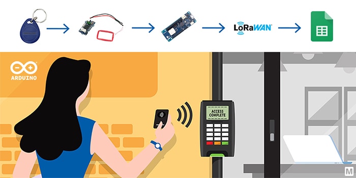
don’t know who is there at the moment. If you are interested to know how to keep track of “Who is in
the office?” in a Google Spreadsheet using the Arduino MKR WAN 1310 over a Long Range Wide Area Network
(LoRaWAN) network and the Grove-125KHz radio-frequency identification (RFID) Reader, keep reading.
Project Materials and Resources
Access the project’s
BOM on Mouser’s website for the required components:
Software and Tools
Project Technology Overview
For this project, use the products and technologies described in the following sections:
Arduino MKR WAN 1310
The Arduino MKR WAN 1310 board (Figure 1) is designed to offer a practical and cost-effective
solution to add LoRa connectivity for Internet of Things (IoT) projects that require low power. This open-source
board is based on the Microchip
SAMD21 low-power processor, the Murata
CMWX1ZZABZ LoRa module, and the MKR family’s characteristic crypto chip (the ECC508).
The crypto chip
adds additional security by storing credentials and certificates in the embedded secure element. Compared to its
predecessor (MKR WAN
1300), the MKR WAN
1310 features a new battery charger, a 2Mb serial peripheral interface (SPI) Flash, and improved control of the
board’s power consumption. The board can be connected to the Arduino IoT Cloud, your own LoRa network
using the Arduino LoRa
PRO Gateway, or
existing LoRaWAN infrastructures, such as The Things Network, which we will be using ithis tutorial.
Figure 1: Arduino MKR WAN 1310 board (Source: Mouser Electronics)
Seeed Studio Grove 125khz RFID reader
An RFID system consists of a radio transponder, a radio receiver, and a transmitter. It uses electromagnetic
fields to identify and track tags automatically. When a tag enters the electromagnetic field transmitted by the
RFID reader, it draws power from the field and starts transmitting its data. To read the information stored on
the RFID tag, the reader must know how the information is stored and the protocol for extracting it. The Grove
125kHz RFID reader (Figure 2) is a module compatible with uem4100 cards and reads the
information with two output formats: UART and Wiegand. It has a sensing distance of a maximum of 7cm. In this
project, we will be using the Parallax RFID Key FOB Tags. These tags carry 64 bits of Read Only memory. This
means that the tag information can be read but not changed.
Figure 2: Seeed Studio Grove 125khz RFID reader (Source: Mouser
Electronics)
The Things Network
The Things Network, commonly known as TTN, is a global community aiming to provide an open-source and
decentralized LoRaWAN network. LoRaWAN is a media access control (MAC) protocol for wide area networks. The
network is designed to allow devices to communicate with internet-connected applications using low power and
little data over long-range wireless connections.
Hardware Setup
Assemble the hardware by doing the following steps:
- Connect the RFID reader with the MKR WAN 1310 as follows:
|
MKR WAN 1310
|
Grove – 125kHz RFID reader
|
|
5V
|
VCC (Red)
|
|
GND
|
GND (Black)
|
|
Pin 13 (RX)
|
TX (Yellow)
|
|
Pin 14 (TX) (optional)
|
RX (White)
|
(make sure the jumper is set to “U” on the two left pins to enter the UART mode)
- Connect the antenna to the MKR WAN 1310 via the micro U.FL connector
- Connect the MKR WAN 1310 with a Micro-USB cable to a computer
- Image of the project board and sensor mounted (Figure 3)
Figure 3: Sensor connected to Arduino (Source: Mouser Electronics)
Software Setup and Programming
You can find the project file for this application on the Mouser GitHub
repository. Download
the code and upload it on your Arduino MKR WAN 1310 or follow this tutorial and do it yourself.
- Arduino
- Install the Arduino IDE
- Setting up the board and port:
- First, add the Atmel SAMD Core. Go to Tools à Board à Boards Manager, type
“SAMD” and click on the install button.
- Then, from Tools > Board select the Arduino MKR WAN 1310, and from Tools > Port choose the port
labeled with the same name of the board (MKR WAN 1310).
- Google Spreadsheet
- Log in to your Google Docs account, create a new spreadsheet and give it a name, such as In-Office
Employee Tracker.
- Go to Tools à Script Editor and replace the few code lines with the code in the
mkrwan1310_proj.gs file. This code ensures that the data received from the Arduino is added in the
Google Sheet correctly.
- Save the project and press run but make sure the selected function is “setup”. (authorize
permissions) (Figure 4)
Figure 4: Google Sheet Configuration (Source: Mouser Electronics)
- Deploy as a web app:
- First, click on “Deploy” on the top right-hand corner and select “New
deployment”.
- Next, select the type as “Web app”, execute as “Me” and make it accessible
to “Anyone”. Copy the URL as we will need it later. (Figure 5)
Figure 5: Google Sheet Deployment (Source: Mouser Electronics)
- The Things Network (TTN)
Requirements: You need to be under the coverage of one of the TTN gateways. Check for coverage using the map of all TTN
gateways on the TTN homepage.
- Create
an account on TTN
- Registering a device:
- Click on your username on the top right-hand corner of the page and log to your console. Select
“applications” and then create your first app by pressing the “add
application” button. Fill the first two fields freely and continue by clicking “Add
application” on the page's bottom right. (Figure 6) Note that the
“Application ID” must be lowercase and without spaces.
Figure 6: TTN Adding Application (Source: Mouser Electronics)
- To connect your device to TTN, you first need to upload and run the “FirstConfiguration” sketch
from the MKRWAN library. From the Arduino IDE, navigate to File > Examples > MKRWAN >
FirstConfiguration. Upload the sketch and open the Serial Monitor (ensure the baud rate is set to 115200).
You might need to change the frequency in the example code according to your country. In the Serial Monitor,
your device EUI will then be displayed. (Figure 7)
Figure 7: Device EUI (Source: Mouser Electronics)
- Next, go back to TTN and register your device using the device Extended Unique Identifier (EUI). Navigate to
“Devices” and click on the “register devices” link. The following page will be
displayed. (Figure 8)
Figure 8: TTN Device Registration (Source: Mouser Electronics)
- Fill the ID of your device in the first field (must be lowercase and without spaces). The second one is the
device EUI that was displayed on the Arduino Serial Monitor. Copy that value into the “Device
EUI” field. Continue by pressing the “Register” button. After registering your device, the
Device Overview page (Figure 7) is shown, which contains all the necessary information needed to complete
the Arduino setup. Go back to the Arduino Serial Monitor, and with the “FirstConfiguration”
script still running, complete the following steps:
- Activation mode: Type 1 to connect via OTAA
- Application EUI: Copy from Device Overview in TTN
- App Key: Copy from Device Overview in TTN)
- If everything goes well, “Message sent correctly!” will be printed in the Serial Monitor, and
the page of the device on TTN will change into this: (Figure 9)
Figure 9: TTN Device Overview after Registration (Source: Mouser
Electronics)
- Adding HTTP integration for the Google Spreadsheet:
- After registering the MKR WAN 1310, we now have to add an HTTP integration to send the data from the Arduino
to our spreadsheet. Go back to your application page in TTN that was created when registering the device.
Click on “Integrations” on the top right of the page. Press the “add integration”
link and select the HTTP integration. Now paste the URL you copied in step 2 from the Google Spreadsheet to
the URL form field and set the other fields like here: (Figure 10)
Figure 10: TTN HTTP Integration (Source: Mouser Electronics)
- The other fields can be left as they are and proceed by clicking on “Add integration”.
Programming
This section will show you how to read the RFID tags (assigned to the “employees”) and log the data
in the spreadsheet using TTN.
- Create a new sketch in the Arduino IDE
- Next, include the MKRWAN library and define the necessary variables and arrays. We store the new tag
information in a buffer array. The tag IDs are then stored in tag1-tag5 13 byte array (IDs of the registered
employees). The rfid_match variable indicates whether the tag on the reader matches one of the tags in our
dataset or not. If a match is found, employee_name is changed to the name of the person assigned to the
current tag holder. Finally, add your app EUI and app Key. (If you don’t know your tag IDs to create
your dataset, upload and run the read_rfid_tags sketch. Place your RFID tags on the reader and copy the
values from the Serial Monitor to your dataset.) (Figure 11)
Figure 11: Code snippet: Declaring Variables (Source: Mouser
Electronics)
- The next part of the code is establishing a connection with TTN. (Figure 12)
Figure 12: Code snippet: Establishing Connection with TTN (Source: Mouser
Electronics)
- We then define two functions: the clearBufferArray() function and the comapreTags() function (Figure
13), (Figure 14)
Figure 13: Code snippet: Clear buffer function (Source: Mouser
Electronics)
Figure 14: Code snippet: Comparing the tags function (Source: Mouser
Electronics)
- Now, using the serial communication of the Arduino, we can read new Tag IDs. Wait for the sensor to read a
tag and store the tag information in a buffer array. (Figure 15)
Figure 15: Code snippet: Reading the ID tags (Source: Mouser
Electronics)
- Here, we compare the tag information with the dataset. We have two cases:
1) We find a match, and the employee's name gets updated. (Figure 16)
2) We don’t find a match in our dataset and print “Error – unknown rfid tag” in the
Serial Monitor.
Figure 16: Code snippet: Comparing the tags with the employees list (Source:
Mouser Electronics)
- If a match is found, we then add the employee’s name to the Google Sheet via the TTN HTTP integration,
clear the buffer array, reset count, and rfid_match. (Figure 17)
Figure 17: Code snippet: Sending the data over LoRa to TTN (Source: Mouser
Electronics)
- The next figure shows you the final result of how the Google Sheet will look like and the Serial
Monitor’s output. Note that you can add changes to the Google App Script to modify the Sheet to your
needs. (Figure 18)
Figure 18: Final Result of the Google Spreadsheet (Source: Mouser
Electronics)
Conclusion
In this project, we automated the process of adding sensor (in this case: RFID sensor) data to a Google Sheet
using the Arduino MKR WAN 1310 and a TTN HTTP integration. It is very straightforward and can be extended to
work with projects using different sensors. Additionally, the HTTP integration makes it easier to connect your
device with internet applications. The MKR WAN 1310 enables you to add LoRaWAN connectivity to your IoT project,
which will be helpful for projects that require low power.
Author Bio
 Hassan Kamel joined Mouser
Electronics in 2021
as a Working Student. He graduated with a Bachelor’s degree in Electrical Engineering from the Technical
University of Munich in 2020 and is now pursuing a Master’s degree at the same university. With a great passion
for electronics, Hassan creates technical content in the form of projects and tutorials using the latest
products sold at Mouser.
Hassan Kamel joined Mouser
Electronics in 2021
as a Working Student. He graduated with a Bachelor’s degree in Electrical Engineering from the Technical
University of Munich in 2020 and is now pursuing a Master’s degree at the same university. With a great passion
for electronics, Hassan creates technical content in the form of projects and tutorials using the latest
products sold at Mouser.


